Electrical Troubleshooting 101

Electrical Troubleshooting 101
Troubleshooting electrical problems in your boat can be a frustrating task, but it does not have to be if you keep a few simple rules in mind: Every circuit needs a power source; most electrical devices require a minimum voltage to function correctly, and all circuits require continuity. Consequently, most electrical problems are caused by low voltage (or no voltage), excessive resistance, or a loss of continuity.
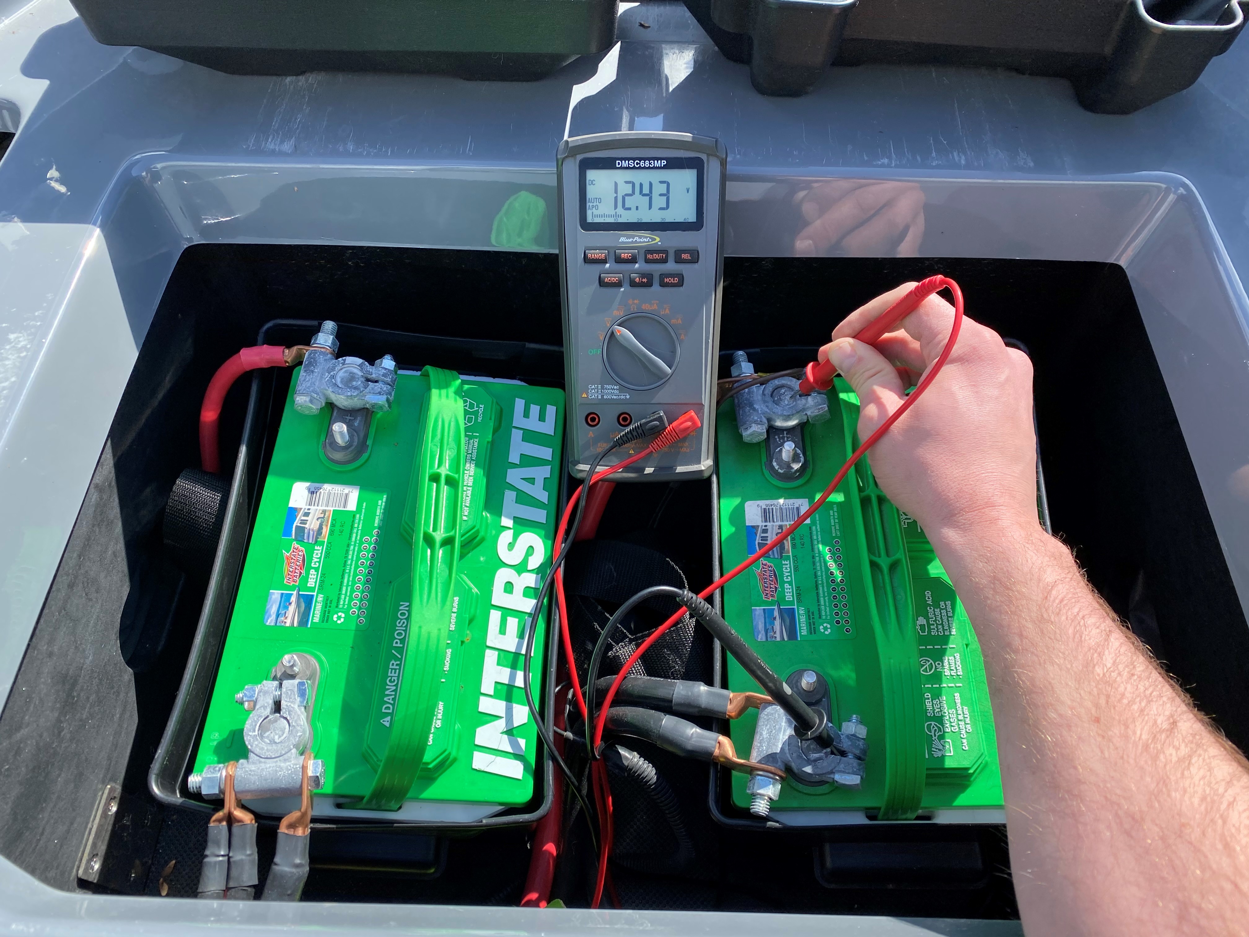
1. What is the battery voltage?
Check battery voltage directly at the battery terminals. A fully charged battery should show around 12.5-12.7 volts. Perform a load test with a battery load tester to make sure there is not a bad or week cell in the battery.
2. Have you loosened, wiggled, and re-tightened the battery cables at the battery and engine?
Even though a battery cable connection may seem tight or clean, corrosion or even paint can cause a bad connection and can cause a loss of power or ground when put under a load. It's also a good idea to fully remove cables and clean connections.
3. Have you checked the positive and ground cables at the breaker panel bus bar?
Be sure these connections are tight and also clean. Loosen the connections and re-tighten to ensure a good connection. They may appear tight because they are wire-tied snug but may be loose at the connection.
4. Have you checked the corresponding breaker at the breaker panel?
The breaker may appear as though it is not tripped but may actually be bad. Remove the breaker and perform a continuity test. Also, check the connections/sockets in the breaker panel. Some connections can become loose and make poor contact causing the contacts to arc and have an intermittent connection or loose connection altogether.
5. Have you checked for power and ground at the corresponding PDM?
Check the red and black wires that plug directly in the PDM. Make sure the connections are fully seated in the sockets of the PDM. Also, remove and inspect the connections. Check and make sure you have both a positive 12v (red) and ground (black) on these wires.
6. Have you checked for input/output signals at the corresponding PDM?
Refer to the correct wiring diagram and PDM pinout to check input/output at the PDM (most wiring diagrams and PDM pinouts can be found on the source. If you have trouble finding them call Skiers Choice Tech Service for assistance). Make sure you have good ground signal on the inputs and a positive 12v signal on the output.
7. Have you performed a continuity check on the correct wires for the system you are testing?
A continuity test can show a broken wire or loose connection. Refer to the wiring diagram for the harness you are testing and check at both ends of the corresponding wire. If no continuity, the wiring harness will need to be replaced. Be sure to check the connector layout as well to make sure the wires are located in the correct socket of the connector.
8. Have you checked all corresponding connectors for loose pins?
A pin that is not fully seated in a connector can cause a bad connection. Be sure to visually inspect pins and pull slightly on the wires on the back of the connectors to make sure pins do not pull out. If a pin pulls out and will not seat when re-inserted, you will need to replace the connector.
9. Have you supplied 12 volts positive and ground directly to the component?
In some situations, an easy way to troubleshoot is to connect a 12v source such as a Power Probe or jump pack to a component such as a wake plate, surf tab, ballast pump, etc. to bypass the boat electrical system. If the component works as it should then there is a problem with the electrical system for that component.